← All projectsENGS 33 / Engineering

Scale bridge

A plywood truss bridge that we modeled, laser-cut, and load-tested.
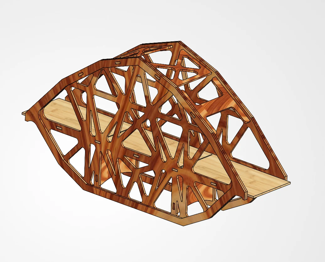
Final plywood truss bridge assembly design
Final bridge design. Image shared by Alexander Llewellyn Smith. View full size (new tab): Final plywood truss bridge assembly design

Design

We used 3 mm and 6 mm plywood, stacking layers where members needed more reinforcement. The initial sketches combined ideas from the team.
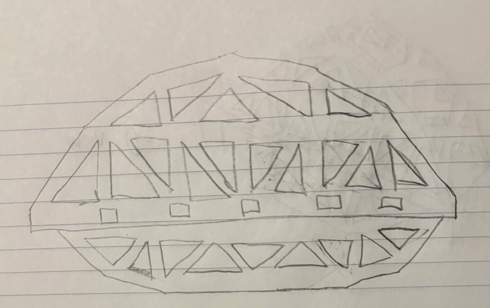
Early hand-drawn bridge concepts
Initial team sketches. View full size (new tab): Early hand-drawn bridge concepts

Analysis

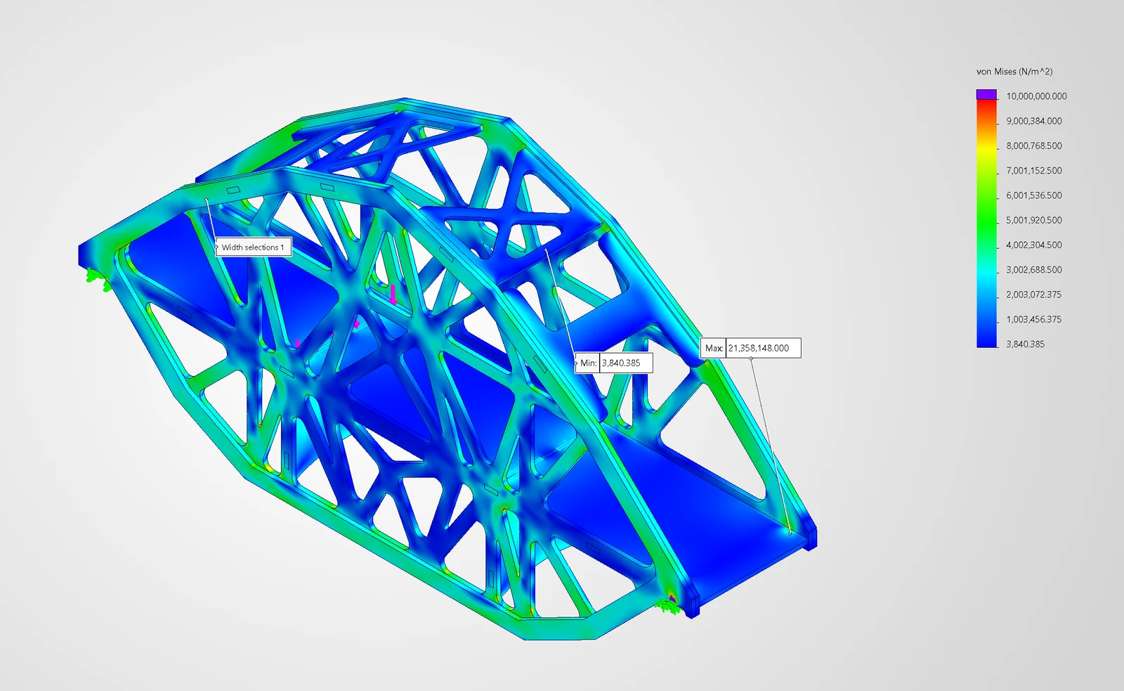
In SAP2000, we varied member thickness, truss height, and geometry. We then used a SolidWorks model and finite-element analysis to check where stresses concentrated.
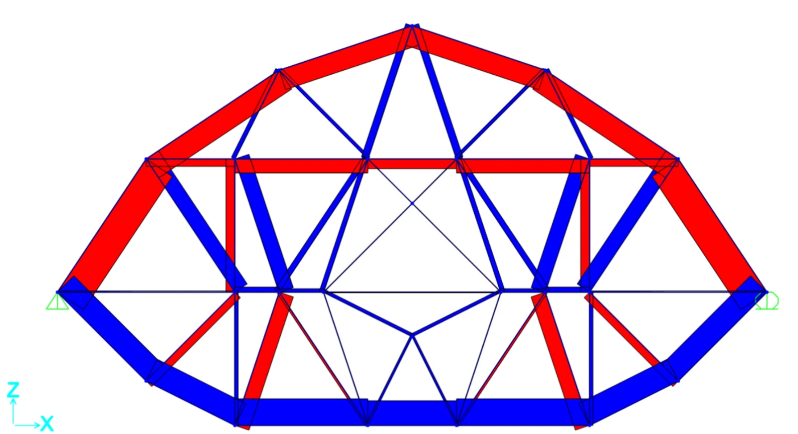
SAP2000 truss model with colored tension and compression members
Structural model. View full size (new tab): SAP2000 truss model with colored tension and compression members
SolidWorks finite-element stress analysis of the bridge
Stress analysis. View full size (new tab): SolidWorks finite-element stress analysis of the bridge

Fabrication and testing

We laser-cut the parts, glued the assembly, and tested it in an Instron machine. Upper members buckled, and a glued crossmember connection separated. I contributed across these stages with the rest of the team. The failure photographs are useful because they show which parts of the assembled bridge gave way, beyond what a model of individual members can predict.
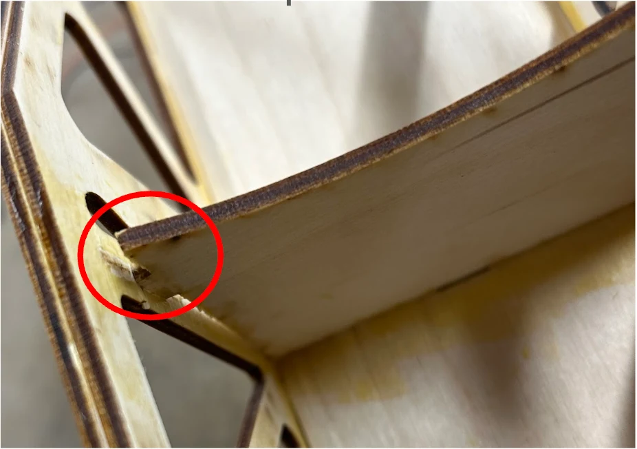
Bridge after load testing showing structural failure
After load testing. View full size (new tab): Bridge after load testing showing structural failure
Mithun RameshkumarDartmouth College